 //*****************************************************************************************************************
 //*****************************************************************************************************************


 //************<<<< Arduino Nano, DS3231 Real Time Clock & Six Relay Module Lights Timer V3.0 >>>>******************


 //*****************************************************************************************************************

 //*****************************************************************************************************************
 /*
 Sketch uses 5722 bytes (18%) of program storage space. Maximum is 30720 bytes.
 Global variables use 286 bytes (13%) of dynamic memory, leaving 1762 bytes for local variables. Maximum is 2048 bytes.

  ************** UPDATED ON Oct 13 2018 *************

 */


 // no oled version
 // six lights/relay control each with two on/off routines
 // for oled version

 //*****************************************************************************************************************


 //*********************<<<< PLEASE VISIT / SUBSCRIBE MY YOUTUBE CHANNEL >>>>***************************************

 // comment for more info


 //*********************<<<<  Youtube.com/CrazyGuyOfficial  >>>>*****************************************


 //*****************************************************************************************************************


 //*****************************************************************************************************************
 // INCLUDE LIBRARIES
 //*****************************************************************************************************************


 #include <Time.h>  // Time Manipulation
 #include <Wire.h>
 #include <DS1307RTC.h> // DS1307 RTC


 //**********************//**********************//**********************
 //  PINS AND CONNECTIONS
 //**********************//**********************//**********************
 const byte lightBlink  = 3 ;

 const byte lightOne   = 5 ;
 const byte lightTwo   = 6 ;
 const byte lightThree  = 4 ;
 const byte lightFour  = 7 ;
 const byte lightFive   = 2 ;
 const byte lightSix   = 8 ;


 // DS3231 RTC "SDA to A4", "SCL to A5" "Vcc to 5V arduino pin Gnd to Gnd"
 // Add more names/pins for more relays


 //##################################################

 // Light Timer ON/OFF Time Settings DEFAULT

 //##################################################


 byte OnOne1   = 14 ; // Hour when Light 1 will turn ON (24 hr format NO zeros before single digits)
 byte OffOne1  = 8 ; // Hour when Light 1 will turn OFF (24 hr format NO zeros before single digits)
 byte OnOne2   = 14 ;  // Hour when Light 1 will turn ON (24 hr format NO zeros before single digits)
 byte OffOne2  = 8 ;  // Hour when Light 1 will turn OFF (24 hr format NO zeros before single digits)


 byte OnTwo1   = 20 ;
 byte OffTwo1  = 8 ;
 byte OnTwo2   = 20 ;
 byte OffTwo2  = 8 ;

 byte OnThree1  = 14 ;
 byte OffThree1 = 8 ;
 byte OnThree2  = 14 ;
 byte OffThree2 = 8 ;

 byte OnFour1  = 14 ;
 byte OffFour1  = 8 ;
 byte OnFour2  = 14 ;
 byte OffFour2  = 8 ;

 byte OnFive1  = 14 ;
 byte OffFive1  = 8 ;
 byte OnFive2  = 14 ;
 byte OffFive2  = 8 ;

 byte OnSix1   = 14 ;
 byte OffSix1  = 8 ;
 byte OnSix2   = 14 ;
 byte OffSix2  = 8 ;


 //*****************************************************************************************************************

 bool RTCerr = 0;

 bool LightOneSts   = 0 ;

 bool LightTwoSts   = 0 ;

 bool LightThreeSts  = 0 ;

 bool LightFourSts  = 0 ;

 bool LightFiveSts  = 0 ;

 bool LightSixSts   = 0 ;


 bool ppOne1     = 0 ;
 bool ppOne2     = 0 ;

 bool ppTwo1      = 0 ;
 bool ppTwo2      = 0 ;

 bool ppThree1      = 0 ;
 bool ppThree2      = 0 ;

 bool ppFour1      = 0 ;
 bool ppFour2      = 0 ;

 bool ppFive1      = 0 ;
 bool ppFive2     = 0 ;

 bool ppSix1      = 0 ;
 bool ppSix2      = 0 ;

 unsigned long SecsOne = 0;


 //##################
 //## RTC ADDRESS ##
 //##################


 #define DS1307_ID 0x68 // I2c Address of the RTC

 byte zero = 0x00; //workaround for issue #527

 //#################################


 //*****************************************************************************************************************
 // SETUP BEGINS
 //*****************************************************************************************************************


 void setup()
 {
  digitalWrite(lightOne,  HIGH);
  digitalWrite(lightTwo,  HIGH); // turn the relay "OFF" and turning the pin "LOW" turns the relay "ON"
  digitalWrite(lightThree, HIGH);
  digitalWrite(lightFour, HIGH);
  digitalWrite(lightFive, HIGH); // turn the relay "OFF" and turning the pin "LOW" turns the relay "ON"
  digitalWrite(lightSix,  HIGH);


  pinMode(lightBlink, OUTPUT);

  pinMode(lightOne,  OUTPUT);
  pinMode(lightTwo,  OUTPUT);
  pinMode(lightThree, OUTPUT);
  pinMode(lightFour, OUTPUT);
  pinMode(lightFive, OUTPUT);
  pinMode(lightSix,  OUTPUT);

  //**********************//**********************//***********************//**********************
  //Check to see if the RTC is present.if yes then Set the ARDUINO's INTERNAL clock accordingly
  //**********************//**********************//***********************//**********************


  Wire.beginTransmission(DS1307_ID);
  Wire.write((uint8_t)0x00);

  setSyncProvider(RTC.get);   //Yes it did, Sync the time from the RTC
  setSyncInterval(20);


  if (timeStatus() != timeSet)
   RTCerr = 1;
  else
   RTCerr = 0;


  Delay15S();

 }

 //*****************************************************************************************************************
 //        SETUP END
 //*****************************************************************************************************************


 void Delay15S()
 {
  delay(1500);

 }


 //*****************************************************************************************************************


 //     LOOP BEGINS


 //*****************************************************************************************************************


 void loop()
 {


  //#####################################
  //####### LIGHTs ON/OFF ###############
  //#####################################


  //########## LIGHT ONE PP1##########################

  if (OffOne1 > OnOne1)
  {


   if (hour() >= OnOne1 && hour () <= OffOne1 - 1)
   {
    TurnLightOneOn1();
   }

   else
   {
    TurnLightOneOff1();

   }

  }


  //**********************************************************


  if (OffOne1 < OnOne1 )
  {


   if (hour() >= OnOne1 || hour () <= OffOne1 - 1)
   {
    TurnLightOneOn1();
   }


   else
   {
    TurnLightOneOff1();

   }
  }


  //########## LIGHT ONE PP2 ##########################

  if (OffOne2 > OnOne2)
  {


   if (hour() >= OnOne2 && hour () <= OffOne2 - 1)
   {
    TurnLightOneOn2();


   }

   else
   {
    TurnLightOneOff2();

   }

  }


  //**********************************************************


  if (OffOne2 < OnOne2 )
  {


   if (hour() >= OnOne2 || hour () <= OffOne2 - 1)
   {
    TurnLightOneOn2();


   }


   else
   {
    TurnLightOneOff2();


   }
  }

  //####################################################################

  //########## LIGHT TWO pp1 ##########################

  if (OffTwo1 > OnTwo1)
  {


   if (hour() >= OnTwo1 && hour () <= OffTwo1 - 1)
   {
    TurnLightTwoOn1();

   }

   else
   {

    TurnLightTwoOff1();

   }

  }


  //**********************************************************


  if (OffTwo1 < OnTwo1)
  {


   if (hour() >= OnTwo1 || hour () <= OffTwo1 - 1)
   {
    TurnLightTwoOn1();


   }


   else
   {
    TurnLightTwoOff1();


   }
  }
  //########## LIGHT TWO pp2 ##########################

  if (OffTwo2 > OnTwo2)
  {


   if (hour() >= OnTwo2 && hour () <= OffTwo2 - 1)
   {
    TurnLightTwoOn2();
   }

   else
   {
    TurnLightTwoOff2();

   }

  }


  //**********************************************************


  if (OffTwo2 < OnTwo2)
  {


   if (hour() >= OnTwo2 || hour () <= OffTwo2 - 1)
   {
    TurnLightTwoOn2();

   }


   else
   {
    TurnLightTwoOff2();


   }
  }


  //####################################################################

  //########## LIGHT THREE pp 1 ##########################

  if (OffThree1 > OnThree1)
  {


   if (hour() >= OnThree1 && hour () <= OffThree1 - 1)
   {
    TurnLightThreeOn1();
   }

   else
   {
    TurnLightThreeOff1();


   }

  }


  //**********************************************************


  if (OffThree1 < OnThree1)
  {


   if (hour() >= OnThree1 || hour () <= OffThree1 - 1)
   {
    TurnLightThreeOn1();

   }


   else
   {

    TurnLightThreeOff1();


   }
  }
  //########## LIGHT THREE pp 2 ##########################

  if (OffThree2 > OnThree2)
  {


   if (hour() >= OnThree2 && hour () <= OffThree2 - 1)
   {
    TurnLightThreeOn2();
   }

   else
   {
    TurnLightThreeOff2();

   }

  }


  //**********************************************************


  if (OffThree2 < OnThree2)
  {


   if (hour() >= OnThree2 || hour () <= OffThree2 - 1)
   {
    TurnLightThreeOn2();

   }


   else
   {

    TurnLightThreeOff2();

   }
  }

  //####################################################################

  //########## LIGHT FOUR pp1 ##########################

  if (OffFour1 > OnFour1)
  {


   if (hour() >= OnFour1 && hour () <= OffFour1 - 1)
   {
    TurnLightFourOn1();
   }

   else
   {
    TurnLightFourOff1();


   }

  }


  //**********************************************************


  if (OffFour1 < OnFour1)
  {


   if (hour() >= OnFour1 || hour () <= OffFour1 - 1)
   {
    TurnLightFourOn1();

   }


   else
   {
    TurnLightFourOff1();


   }
  }
  //########## LIGHT FOUR pp2 ##########################
  if (OffFour2 > OnFour2)
  {


   if (hour() >= OnFour2 && hour () <= OffFour2 - 1)
   {
    TurnLightFourOn2();

   }

   else
   {
    TurnLightFourOff2();

   }

  }


  //**********************************************************


  if (OffFour2 < OnFour2)
  {


   if (hour() >= OnFour2 || hour () <= OffFour2 - 1)
   {
    TurnLightFourOn2();

   }


   else
   {
    TurnLightFourOff2();


   }
  }

  //####################################################################

  //########## LIGHT FIVE pp1 ##########################

  if (OffFive1 > OnFive1)
  {


   if (hour() >= OnFive1 && hour () <= OffFive1 - 1)
   {
    TurnLightFiveOn1();
   }

   else
   {
    TurnLightFiveOff1();


   }

  }


  //**********************************************************


  if (OffFive1 < OnFive1)
  {


   if (hour() >= OnFive1 || hour () <= OffFive1 - 1)
   {
    TurnLightFiveOn1();

   }


   else
   {
    TurnLightFiveOff1();

   }
  }

  //########## LIGHT FIVE pp2 ##########################

  if (OffFive2 > OnFive2)
  {


   if (hour() >= OnFive2 && hour () <= OffFive2 - 1)
   {
    TurnLightFiveOn2();

   }

   else
   {
    TurnLightFiveOff2();


   }

  }


  //**********************************************************


  if (OffFive2 < OnFive2)
  {


   if (hour() >= OnFive2 || hour () <= OffFive2 - 1)
   {
    TurnLightFiveOn2();

   }


   else
   {
    TurnLightFiveOff2();


   }
  }


  //####################################################################
  //########## LIGHT SIX pp1 ##########################

  if (OffSix1 > OnSix1)
  {


   if (hour() >= OnSix1 && hour () <= OffSix1 - 1)
   {
    TurnLightSixOn1();
   }

   else
   {
    TurnLightSixOff1();


   }

  }


  //**********************************************************


  if (OffSix1 < OnSix1)
  {


   if (hour() >= OnSix1 || hour () <= OffSix1 - 1)
   {
    TurnLightSixOn1();

   }


   else
   {
    TurnLightSixOff1();

   }
  }

  //########## LIGHT SIX pp2 ##########################

  if (OffSix2 > OnSix2)
  {


   if (hour() >= OnSix2 && hour () <= OffSix2 - 1)
   {
    TurnLightSixOn2();
   }

   else
   {


    TurnLightSixOff2();


   }

  }


  //**********************************************************


  if (OffSix2 < OnSix2)
  {


   if (hour() >= OnSix2 || hour () <= OffSix2 - 1)
   {
    TurnLightSixOn2();

   }


   else
   {
    TurnLightSixOff2();
   }
  }

  //####################################################################


  //#####################################
  // Blink Led And Call RTC TEST
  //#####################################

  if (millis() / 1000 - SecsOne > 10 ) //
  {
   digitalWrite (lightBlink, HIGH); // blink status LED


   rtctest();

   SecsOne = millis() / 1000; // then reset the timer


  }


 }


 //**********************//**********************//**********************
 //        LOOP END
 //**********************//**********************//**********************
 void TurnLightOneOn1()
 {
  if (!LightOneSts)
  {
   digitalWrite(lightOne, LOW);

   LightOneSts = 1 ;

   Delay15S();

  }  ppOne1 = 1 ;

 }


 void TurnLightOneOff1()
 {
  if (!ppOne2)
  {
   digitalWrite(lightOne, HIGH);
   LightOneSts = 0 ;
  }
  ppOne1 = 0 ;


 }


 void TurnLightOneOn2()
 {

  if (!LightOneSts)
  {
   digitalWrite(lightOne, LOW);
   LightOneSts = 1 ;

   Delay15S();

  }  ppOne2 = 1 ;


 }

 void TurnLightOneOff2()
 {
  if (!ppOne1)
  {
   digitalWrite(lightOne, HIGH);
   LightOneSts = 0 ;
  }
  ppOne2 = 0 ;
 }


 void TurnLightTwoOn1()
 {
  if (!LightTwoSts)
  {
   digitalWrite(lightTwo, LOW);

   LightTwoSts = 1 ;

   Delay15S();

  }  ppTwo1 = 1 ;

 }


 void TurnLightTwoOff1()
 {
  if (!ppTwo2)
  {
   digitalWrite(lightTwo, HIGH);
   LightTwoSts = 0 ;
  }
  ppTwo1 = 0 ;


 }

 void TurnLightTwoOn2()
 {

  if (!LightTwoSts)
  {
   digitalWrite(lightTwo, LOW);
   LightTwoSts = 1 ;

   Delay15S();

  }  ppTwo2 = 1 ;

 }


 void TurnLightTwoOff2()
 {

  if (!ppTwo1)
  {
   digitalWrite(lightTwo, HIGH);
   LightTwoSts = 0 ;
  }
  ppTwo2 = 0 ;
 }


 void TurnLightThreeOn1()
 {

  if (!LightThreeSts)
  {
   digitalWrite(lightThree, LOW);
   LightThreeSts = 1 ;

   Delay15S();

  }  ppThree1 = 1 ;

 }


 void TurnLightThreeOff1()
 {
  if (!ppThree2)
  {
   digitalWrite(lightThree, HIGH);
   LightThreeSts = 0 ;
  }
  ppThree1 = 0 ;
 }


 void TurnLightThreeOn2()
 {

  if (!LightThreeSts)
  {
   digitalWrite(lightThree, LOW);
   LightThreeSts = 1 ;
   Delay15S();

  } ppThree2 = 1 ;
 }


 void TurnLightThreeOff2()
 {
  if (!ppThree1)
  {
   digitalWrite(lightThree, HIGH);
   LightThreeSts = 0 ;
  }
  ppThree2 = 0 ;

 }

 void TurnLightFourOn1()
 {
  if (!LightFourSts)
  {
   digitalWrite(lightFour, LOW);
   LightFourSts = 1 ;

   Delay15S();

  }
  ppFour1 = 1;

 }
 void TurnLightFourOff1()
 {
  if (!ppFour2)
  {

   digitalWrite(lightFour, HIGH);
   LightFourSts = 0 ;
  }
  ppFour1 = 0;

 }
 void TurnLightFourOn2()
 {
  if (!LightFourSts)
  {
   digitalWrite(lightFour, LOW);
   LightFourSts = 1 ;
   Delay15S();

  }  ppFour2 = 1;

 }

 void TurnLightFourOff2()
 {
  if (!ppFour1)
  {

   digitalWrite(lightFour, HIGH);
   LightFourSts = 0 ;
  }
  ppFour2 = 0;

 }

 void TurnLightFiveOn1()
 {
  if (!LightFiveSts)
  {
   digitalWrite(lightFive, LOW);
   LightFiveSts = 1 ;

   Delay15S();

  }  ppFive1 = 1;


 }

 void TurnLightFiveOff1()
 {


  if (!ppFive2)
  {


   digitalWrite(lightFive, HIGH);
   LightFiveSts = 0 ;
  }
  ppFive1 = 0;


 }
 void TurnLightFiveOn2()
 {

  if (!LightFiveSts)
  {
   digitalWrite(lightFive, LOW);
   LightFiveSts = 1 ;
   Delay15S();

  }  ppFive2 = 1;

 }
 void TurnLightFiveOff2()
 {
  if (!ppFive1)
  {


   digitalWrite(lightFive, HIGH);
   LightFiveSts = 0 ;
  }
  ppFive2 = 0;
 }


 void TurnLightSixOn1()
 {
  if (!LightSixSts)
  {
   digitalWrite(lightSix, LOW);
   LightSixSts = 1 ;

   Delay15S();

  }
  ppSix1 = 1;

 }

 void TurnLightSixOff1()
 {

  if (!ppSix2)

  {


   digitalWrite(lightSix, HIGH);
   LightSixSts = 0 ;
  }
  ppSix1 = 0;


 }

 void TurnLightSixOn2()
 {

  if (!LightSixSts)
  {
   digitalWrite(lightSix, LOW);
   LightSixSts = 1 ;
   Delay15S();

  }  ppSix2 = 1;

 }
 void TurnLightSixOff2()
 {
  if (!ppSix1)

  {


   digitalWrite(lightSix, HIGH);
   LightSixSts = 0 ;
  }
  ppSix2 = 0;

 }


 //#####################
 // RTC Test ##########
 //#####################
 void rtctest()
 {

  if (Wire.endTransmission() == 0) //Did the RTC respond?

  {


   RTCerr = 0;    // set RTC error status boolean to false
   digitalWrite (lightBlink, LOW); // blink status LED

  }

  else
  {

   RTCerr = 1;
   digitalWrite (lightBlink, HIGH);

  }

 }
Showing posts with label do it yourself. Show all posts
Showing posts with label do it yourself. Show all posts
Arduino Grow Light Timer Six Switch/Relay Dual on/off Control V3.0 no oled/button version
WiFi / Smart Ip Camera Tear down / a look from inside V380 smart ip camera type-01
I bought my first Wifi/ip camera named " V380 Smart Wifi Camera ".
It is a very cheap camera (as compared to the others with similar functionality)but it is a 720p Day/Night Vision Camera with mechanical IR cut filter , LDR , multiple infrared L.E.D.s , On-board memory card slot , Mic/Speaker for two way audio , Alarm notifications and cloud based alarm pictures and it has Wifi which can work both in Station mode and AP mode.
First , I bought this, one camera (from one vendor) and used it for some time then after finding it useful I bought three more of these.(from the second guy)
After reading and watching videos on-line about "hacking ip cameras" and how they have "weak security" and "back-doors", I got really curious and first,I opened them all up to see "what's inside" as I am still new to these kind of electronics and SoCs.To be honest they are impressive and so tiny and beautiful. :-)
Then after learning a little about "computer networking,ports and stuff",using Nmap on Computer and Fing,Connect-bot,Packet capture app on the phone I found a Telnet port (23), RTSP (554) and MMCC (5050).The MMCC(multimedia conference control) port only shows up in the Fing app when not streaming the camera video using the V380 camera app.
Using "Connect Bot" app I logged in as "Root" through the telnet port (23) using the login user name "root" and leaving the password empty.
It has some version of busy-box with "ash-shell".
I wasn't able to do much after that point except browsing the Linux file system which is "Read-only". All of this works only in the local network.
I also connected the USB to serial converter module (cp2102) to the Rx,Tx and Gnd (marked on the board) after soldering cut-out legs from some LEDs and using male to female jumper wires and if you turn the camera on after connecting the wires it doesn't work and nothing shows up in the serial monitor but if you connect the wires right after turning it on it boots up and it shows all the information in the serial monitor and if the Tx is also connected you can browse the file system as "root" right from the serial monitor but it's a read only system from what I understood because I tried a-lot of "things" but wasn't able to do/write/modify anything as it says "read-only".
However , I'll try to do it again after learning a little more.
When in Station Mode and connected to Internet the Camera automatically connects to the preprogrammed IPs/servers in China and the Android app also sends requests to multiple IPs and after the server responds it sends un-encrypted user name/password string (set from the app) for viewing the video.The server responds with an address and ports and the app connects to that and receives live images/audio.It also has alarm function which works only when connected to the Internet other than the alarm notifications/and alarm pictures (stored in the cloud) function, the live video works perfectly in the local network but all of this works using only the v380 app or the other ,comparatively less functional, apps from the same developer.
Following are the pictures of the first camera and I'll post the other camera's pictures too as there are many differences in their hardware and it seems like they are the later versions of this camera.
Although they all have the same main Soc.(the big grain media chip GM8135S)


D.I.Y. RC Plane/ Home-made Rc plane from Card Board and Hot Glue (fuselage) 01
There were no servo motors and only two small motors with propellers. Yaw was achieved by changing the throttle on both sides and it was really hard to control.
Then after many years I flew a quad-copter,first, a Nano-quadcopter and then a big one .
Then I thought about making an RC plane and read/watched a-lot of things on-line.but then I couldn't find the foam sheets which are normally used to do this.So now, I'm trying to make it with a card board.
Obviously, it's weight can be and it is, a-lot more as compared to the "usual" foam sheets but I still carried on with it thinking, it will definitely teach me some things about making Rc planes and the future ones might even takeoff more than once :)
However, I have a strong "will" to make it fly (multiple times )no-matter how much "thrust" it requires.
I just want to see this "thing" fly.


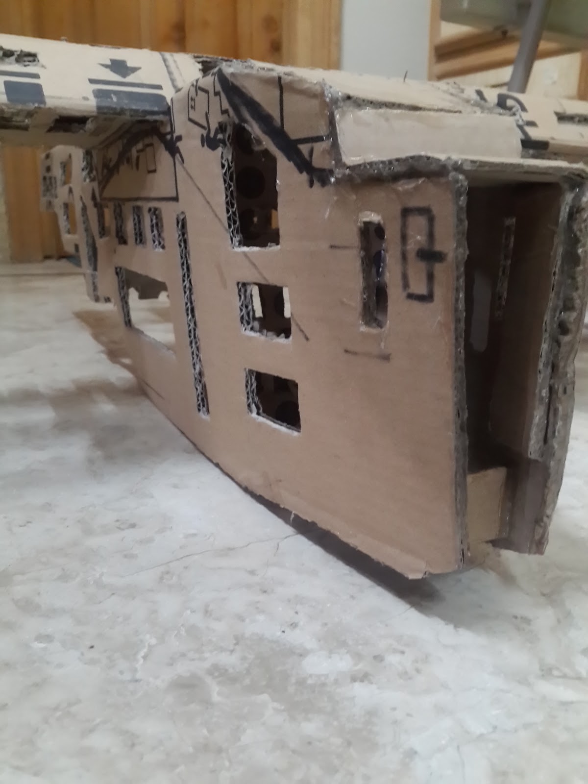
TO BE CONTINUED . . . . .
D.I.Y. Make RCA/AV Cable for Raspberry pi (using earphones/headphones audio lead)
Make RCA cable for Raspberry pi
I used an old cell phone's hands-free earphones kit and a female RCA connectors cable to make an AV (audio/video) Cable for the Raspberry Pi.
First, I tried to use a "ready-made" AV cable that I had for a long time and it came with another cell phone (Nokia N95 8GB music edition) but it didn't work at first because the Raspberry pi and that cellphone have different pin-out in the Audio Jack.
So, when I plugged it in the Raspberry Pi 3 and in the TV ,I just got weird noises and no Video . After thinking about it for sometime,I tested it with a multimeter by putting it in the "continuity mode" and in that mode if you touch both of the leads of the multimeter together it shows the number "0" and if there is no connection between the two leads it shows the alphabet "l" which means out-of-limit or range. It actually measures the resistance between it's two leads.So, if there is no connection between the two points i.e. the audio jack's metal pin and the corresponding wires the resistance will be infinite or too high for the meter to measure.
So, if you connect one lead of the multimeter (black or red doesn't matter in this case) to one of the four metal contacts of the Audio lead and the other lead of the multimeter to the RCA connector's outer metal part (Ground) or the center part (which is for the Signal) you can see which part of the Audio lead is connected to which part of the RCA connector.
In my case what was happening was that the Raspberry Pi's Video signal was going to the Ground of the Rca Cable and because ground is common for all the signals (Audio Left,Audio Right ,Video) all the three RCA connectors (red,white,yellow) had Video signal in their outer metal part of the connector and the "Actual Ground" was only on the Signal part in the center of the Yellow connector because of the different pin-out.
However, I made it to work also, just to test the Video output of the Raspberry pi by using a single Male RCA connector with it's wire stripped and by wrapping it on both the outer part of the yellow connector (of that cell phones AV cable) to get the Video Signal and the center part to get the Ground and then it worked but it was too messy.
So,then i felt the need to make a proper AV cable for the pi because I also fixed a cheap LCD display and that display was part of a car's Headrest and meant to be used with the DVD player it came along with(the chinese car DVD player with built-in lcd came with two head rests with LCDs in them ) and it has two analog video inputs so it can work with the Rpi too.
How i made the AV cable can be seen in the picture below.
 |
| Raspberry Pi Audio Jack/RCA Connections Pin-out |
 |
| Cell phone hands-free earphones with button and a Mic and four connector lead |
 |
| Cellphone Earphones with Button and Mic for Calls |
 |
| Female RCA connectors Cable |
 |
| Female RCA Connectors Separated from the "other" lead |
 |
| Separate all the wires and test with a multimeter (on continuity mode) because sometimes the wires are insulated and they have to be "burned" to remove the insulation |
 |
| Test all the wires before proceeding any further just to be sure because it will become difficult to troubleshoot later if there is any problem with the connections |
 |
| Join the related wires together |
 |
| Solder them together and Test them Again |
 |
| Tape the wires separately and then together to make it all neat |
Then I used Male-to-Male RCA cable to connect this to the TV.
You can also use Male to Male RCA cable then cut it,strip it and join with the audio lead the same way and then it will directly connect to the TV giving the same results .
I did it this way because I also had the useless female connectors .
 |
| Car Head-rest Rear LCD for DVD player Front View |
 |
| Back Cover Removed View of LCD and it's control board |
 |
| Main IC on the control board of LCD |
 |
| Back View of LCD control Board and Connectors |
Subscribe to:
Posts (Atom)