 /* #########################################################################
   #################### Esp8266 Serial to WiFi Monitor #####################
   ########################## WEMOS D1 MINI ################################
   ############################### for #####################################
   ################### ARDUINO NANO SMART GROW CONTROLLER ##################
   #################                              ##########################
   ############################ |WWWW| #####################################
   ############################ \O_O/ ######################################
   #  CAN BE USED AS A GENERAL PURPOSE MONITOR FOR ANYTHING WITH A TX PIN ##
   #############        AFTER SOME MODIFICATIONS        ####################
 */


 /* #########################################################################
 I'll improve it as i learn more
  #########################################################################
 // PLEASE LIKE AND SUBSCRIBE
 // MY YOUTUBE CHANNEL
 // YOUTUBE.COM/CRAZYGUYOFFICIAL
 // Visit Blog for Sketch Updates and more Sketches and "things"


 // Set Port forward from your router to this Webserver at port 80
 // to monitor it from anywhere**

 // This server is not secure
 // controlling things should NEVER be done using
 // an UN-encrypted webserver like this
 // It's only good for Monitoring
 // Subscribe to my channel for updates for this sketch
 // and other sketches related to this project
 // because i'll add more things to it gradually

  #########################################################################
  #########################################################################


 */

 #include <ESP8266WiFi.h>  // Version 1.0.0
 #include <SoftwareSerial.h>  // Version 1.0.0


 const char* ssid = "SQUANCHY01";
 const char* password ="c137gsasotf";


 char Time[9];           // Character Arrays or C-strings
 char Day;             // size should be the total number of Chars to be stored +1 for null char
 char Date[3];
 char Mon[3];
 char Year[5];
 char Status[13];
 char Temp1[6];
 char Temp2[6];
 char Hum[6];

 unsigned long Secs = 0;

 bool newData = 0;
 bool err =1;

 bool Lsts =0;
 bool Csts =0;
 bool Hsts =0;
 bool Fsts =0;
 bool Ssts =0;
 bool DHTerr=0;
 bool RTCerr=0;

 WiFiServer server(80);

 SoftwareSerial swSer(D1, D2, false, 256);   // "swSer can be changed it will be the name for the Software Serial
                        // Software Serial Library Enables Esp8266's GPIO D1 and D2
                        // to be used as Rx and Tx pins RESPECTIVELY
                        // ONLY Rx is used and is connected to the Tx of a 5V Arduino Nano
 void setup() {                // using a Voltage Divider circuit 1K and 2K Resistors
                        // And Ground of esp to Ground of Arduino


 Serial.begin(115200);             // This is the baud rate for ESP's Serial at USB which can be viewed in Arduino IDE Serial monitor

 swSer.begin(9600);              // This is the baud rate for esps Software serial at pins D1 and D2 so it can communicate with arduino
                        // it's slow because of Arduino Nano's slow speed as compared to Esp
                        // can change the name swSer from above
 delay(10);


 Serial.println();

 Serial.print("Connecting to ");

 Serial.println(ssid);


 WiFi.mode(WIFI_STA);

 WiFi.begin(ssid, password);


 while (WiFi.status() != WL_CONNECTED)

  {

  delay(500);

  Serial.print(".");

  }


  Serial.println("");

  Serial.println("WiFi connected");


  server.begin();

  Serial.println("Waiting for the IP Add...");

  delay(5000);


  Serial.println(WiFi.localIP());

  }


 /*##############################################################################################
  ###############################################################################################
  ################ SETUP END ####################################################################
  ###############################################################################################
  */


 /*##############################################################################################
  ###############################################################################################
  ################ LOOP BEGINS ##################################################################
  ###############################################################################################
  */


 void loop()
 {
  char data[53];
  byte i = 0 ;
  byte x = 0 ;

  if (swSer.available() > 0 )

  {
  char Z = swSer.read();

   if(Z=='Z')   // match first Character to check "validity"
   {        // and this letter 'Z' is not stored in the array below

   newData=1;
   Secs=millis()/1000;

    for(i= 0; i< 52; )

    {
     data[i] = swSer.read();

     i++;

     data[i] = '\0';
    }


    for(i=0; i<52;)
    {                // serial print to arduino ide monitor via usb,all the chars stored in data array
     Serial.print("char number: "); // and print char number the INDEX number starting from zero
                    // the actual first char is the Letter "Z' which is not stored
     Serial.println(i);

     Serial.println(data[i]);

     i++;
    }

   }
  else
  {
   err=1;
  }
  }


 //############# GET TIME #######################################################################

  if(newData)
  {
                       // get time from the data array
   for( i = 0; i < 8; )
   {
    Time[i] = data[i];

    i++;

   }

   Serial.print("Time :");

   Serial.println(Time);           // serial print all the chars stored in the time array


 //############# GET DAY OF THE WEEK #############################################################

   if( data[8]=='W' )

   {
    err=0;
    Day = data[9];


   Serial.print("Day :");

   Serial.println(Day);           // serial print all the chars stored in the day array
   }
   else
   {
   err=1;
   }

 //############# GET DATE #######################################################################

   if(data[10]=='D')
   {
    err=0;
    x=0;
    for( i = 11; i < 13; )
    {
     Date[x] = data[i];
     i++;
     x++;
    }

    Serial.print("Date :");

    Serial.println(Date);         // serial print all the chars stored in the Date array
   }
   else
   {
    err=1;
   }


 //############# GET MONTH #######################################################################


   if(data[13]=='M')
   {
    err=0;
    x=0;
    for( i =14 ; i < 16; )
    {
     Mon[x] = data[i];
     i++;
     x++;
    }

    Serial.print("Month :");

    Serial.println(Mon);          // serial print all the chars stored in the month / mon array
   }
   else
   {
    err=1;
   }

 //############# GET YEAR #######################################################################

   if(data[16]=='Y')
   {
    err=0;
    x=0;
    for( i = 17; i < 21; )
    {
     Year[x] = data[i];
     i++;
     x++;
    }

    Serial.print("Year :");

    Serial.println(Year);         // serial print all the chars stored in the Year array

   }
   else
   {
    err=1;
   }


 //############# GET STATUS #######################################################################

   if(data[21]=='L')
   {
    err=0;
    x=0;
    for( i = 22; i < 34; )
    {
     Status[x] = data[i];
     i++;
     x++;
    }

    Serial.print("Status :");

    Serial.println(Status);       // serial print all the chars stored in the Status array
   }
   else
   {
    err=1;
   }


 //############# GET T1 ###########################################################################

   if(data[34]=='t')
   {
    err=0;
    x=0;
    for( i = 35; i < 40; )
    {
     Temp1[x] = data[i];
     i++;
     x++;
    }

    Serial.print("Temp 1 :");

    Serial.println(Temp1);    // serial print all the chars stored in the temperature / temp1 array
   }
   else
   {
    err=1;
   }


 //############# GET Hum #######################################################################


   if(data[40]=='h')
   {
    err=0;
    x=0;
    for( i = 41; i < 46; )
    {
     Hum[x] = data[i];
     i++;
     x++;
    }

    Serial.print("Humidity :");

    Serial.println(Hum);    // serial print all the chars stored in the Humidity / Hum array
   }
   else
   {
    err=1;
   }

 //############# GET T2 #######################################################################


   if(data[46]=='r')
   {
    err=0;
    x=0;
    for( i = 47; i < 52; )
    {
     Temp2[x] = data[i];
     i++;
     x++;
    }

    Serial.print("Temp2 :");

    Serial.println(Temp2); // serial print all the chars stored in time array
   }
   else
   {
    err=1;
   }

  newData=0;

 }


  setStatus();

  sendHtml();


   if(millis()/1000 -Secs > 30 )
   {
   Serial.println("Resetting Arrays");
   Serial.println(Secs);
   ResetArrays();
   Secs=millis()/1000;
   }


 }

  //####################################################################################
  //##################### END OF LOOP #######################################
  //####################################################################################


 void setStatus()
 {
  if(!err)
  {
  Lsts=Status[0]-'0';
  Csts=Status[2]-'0';
  Hsts=Status[4]-'0';
  Fsts=Status[6]-'0';
  Ssts=Status[8]-'0';
  DHTerr=Status[10]-'0';
  RTCerr=Status[11]-'0';

  }


 }


 void sendHtml()
 {

  WiFiClient client = server.available();

  if (client)
  {
   Serial.println("New client");
   boolean blank_line = true;

   while (client.connected())
   {
    if (client.available())
    {
     char c = client.read();

     if (c == '\n' && blank_line)
     {
      client.println("HTTP/1.1 200 OK");
      client.println("Content-Type: text/html");
      client.println("Connection: close");
      client.println();


      client.println("<!DOCTYPE HTML>");
      client.println("<html>");
      client.println("<head><meta http-equiv='refresh' content='5'/></head><body><h1>Esp8266 Serial to Wifi Monitor Ver: 1.0</h1>");

      client.println("<h2>>>>> ---- Time :");
      client.println(Time);
      client.println("--<<< >>> ---- Day : ");
      client.println(Day);
      client.println("--<<< >>> ---- Date : ");
      client.println(Date);
      client.println("-");
      client.println(Mon);
      client.println("-");
      client.println(Year);
      client.println("---- <<<<<");
      client.println("</h2>");
      client.println("<br />");

      client.println("<h2>Temp 1 :");
      client.println(Temp1);
      client.println("\260C</h2>");

      client.println("<h2>Temp 2 :");
      client.println(Temp2);
      client.println("\260C</h2>");

      client.println("<h2>Humidity :");
      client.println(Hum);
      client.println("%</h2>");

      client.println("<br />");

      client.println("<h1>Current States of Switches</h1>");

      client.println("<br />");

      client.println("<h3>LIGHT:>>> ");
       if(!err)
       {
        if(Lsts)
        {
        client.println("ON </h3>");
        }
        else
        {
        client.println("OFF </h3>");
        }
       }
       else
       {
        client.println("UNKNOWN </h3>");
       }


      client.println("<h3>COOLER:>>>");


       if(!err)
       {
        if(Csts)
        {
        client.println("ON </h3>");
        }
        else
        {
        client.println("OFF </h3>");
        }
       }
       else
       {
       client.println("UNKNOWN </h3>");
       }


      client.println("<h3>HEATER:>>>");

       if(!err)
       {
        if(Hsts)
        {
        client.println("ON </h3>");
        }
        else
        {
        client.println("OFF </h3>");
        }
       }
       else
       {
       client.println("UNKNOWN </h3>");
       }


      client.println("<h3>FAN:>>>");


       if(!err)
       {
        if(Fsts)
        {
        client.println("ON </h3>");
        }
        else
        {
        client.println("OFF </h3>");
        }
       }
       else
       {
       client.println("UNKNOWN </h3>");
       }


      client.println("<h3>HUMIDIFIER:>>>");

       if(!err)
       {
        if(Ssts)
        {
        client.println("ON </h3>");
        }
        else
        {
        client.println("OFF </h3>");
        }
       }
       else
       {
       client.println("UNKNOWN </h3>");
       }


      client.println("<br />");


      client.println("<h4>DHT Err:>>>");
       if(!err)
       {
        if(DHTerr)
        {
        client.println("TRUE </h4>");
        }
        else
        {
        client.println("FALSE </h4>");
        }
       }
       else
       {
       client.println("UNKNOWN </h4>");
       }


      client.println("<h4>RTC Err:>>>");

       if(!err)
       {
        if(RTCerr)
         {
         client.println("TRUE </h4>");
         }
        else
        {
        client.println("FALSE </h4>");
        }
       }
       else
       {
       client.println("UNKNOWN </h4>");
       }

      client.println("<br />");

      client.println("<h4>Serial Read Error:>>>");
       if(err)
       {
       client.println("TRUE ----OH JEEZ </h4>");
       }
       else
       {
       client.println("FALSE </h4>");
       }


      char LinkOne[]= "https://youtube.com/crazyguyofficial";
      client.println("<h3><a href=");
      client.print(LinkOne);
      client.print(">CHANNEL</a></h3>");

      char LinkTwo[]= "https://amkdiyprojects.blogspot.com";
      client.println("<h3><a href=");
      client.print(LinkTwo);
      client.print(">BLOG</a></h3>");

      client.println("</body></html>");
      break;


     }


     if (c == '\n')
     {
     blank_line = true;
     }
     else if (c != '\r')
     {
     blank_line = false;
     }


    }
   }


  delay(1);
  client.stop();  // closing the client connection

  Serial.println("Client disconnected.");

  }
 }


 void ResetArrays()
 {
  //Serial.flush();
  err=1;
 // data[0]  ='\0';
  Time[0]  ='\0';             // Character Arrays or C-strings
  Day    ='\0';             // size should be the total number of Chars to be stored +1 for null char
  Date[0]  ='\0';
  Mon[0]  ='\0';
  Year[0]  ='\0';
  Status[0] ='\0';
  Temp1[0] ='\0';
  Temp2[0] ='\0';
  Hum[0]  ='\0';
 }
Showing posts with label wifi. Show all posts
Showing posts with label wifi. Show all posts
Esp8266 Wemos D1 Mini Serial to Wifi Html WebServer Monitor for Arduino Smart Grow Box Controller [OUT-DATED]
WiFi / Smart Ip Camera Tear down / a look from inside V380 smart ip camera type-01
I bought my first Wifi/ip camera named " V380 Smart Wifi Camera ".
It is a very cheap camera (as compared to the others with similar functionality)but it is a 720p Day/Night Vision Camera with mechanical IR cut filter , LDR , multiple infrared L.E.D.s , On-board memory card slot , Mic/Speaker for two way audio , Alarm notifications and cloud based alarm pictures and it has Wifi which can work both in Station mode and AP mode.
First , I bought this, one camera (from one vendor) and used it for some time then after finding it useful I bought three more of these.(from the second guy)
After reading and watching videos on-line about "hacking ip cameras" and how they have "weak security" and "back-doors", I got really curious and first,I opened them all up to see "what's inside" as I am still new to these kind of electronics and SoCs.To be honest they are impressive and so tiny and beautiful. :-)
Then after learning a little about "computer networking,ports and stuff",using Nmap on Computer and Fing,Connect-bot,Packet capture app on the phone I found a Telnet port (23), RTSP (554) and MMCC (5050).The MMCC(multimedia conference control) port only shows up in the Fing app when not streaming the camera video using the V380 camera app.
Using "Connect Bot" app I logged in as "Root" through the telnet port (23) using the login user name "root" and leaving the password empty.
It has some version of busy-box with "ash-shell".
I wasn't able to do much after that point except browsing the Linux file system which is "Read-only". All of this works only in the local network.
I also connected the USB to serial converter module (cp2102) to the Rx,Tx and Gnd (marked on the board) after soldering cut-out legs from some LEDs and using male to female jumper wires and if you turn the camera on after connecting the wires it doesn't work and nothing shows up in the serial monitor but if you connect the wires right after turning it on it boots up and it shows all the information in the serial monitor and if the Tx is also connected you can browse the file system as "root" right from the serial monitor but it's a read only system from what I understood because I tried a-lot of "things" but wasn't able to do/write/modify anything as it says "read-only".
However , I'll try to do it again after learning a little more.
When in Station Mode and connected to Internet the Camera automatically connects to the preprogrammed IPs/servers in China and the Android app also sends requests to multiple IPs and after the server responds it sends un-encrypted user name/password string (set from the app) for viewing the video.The server responds with an address and ports and the app connects to that and receives live images/audio.It also has alarm function which works only when connected to the Internet other than the alarm notifications/and alarm pictures (stored in the cloud) function, the live video works perfectly in the local network but all of this works using only the v380 app or the other ,comparatively less functional, apps from the same developer.
Following are the pictures of the first camera and I'll post the other camera's pictures too as there are many differences in their hardware and it seems like they are the later versions of this camera.
Although they all have the same main Soc.(the big grain media chip GM8135S)


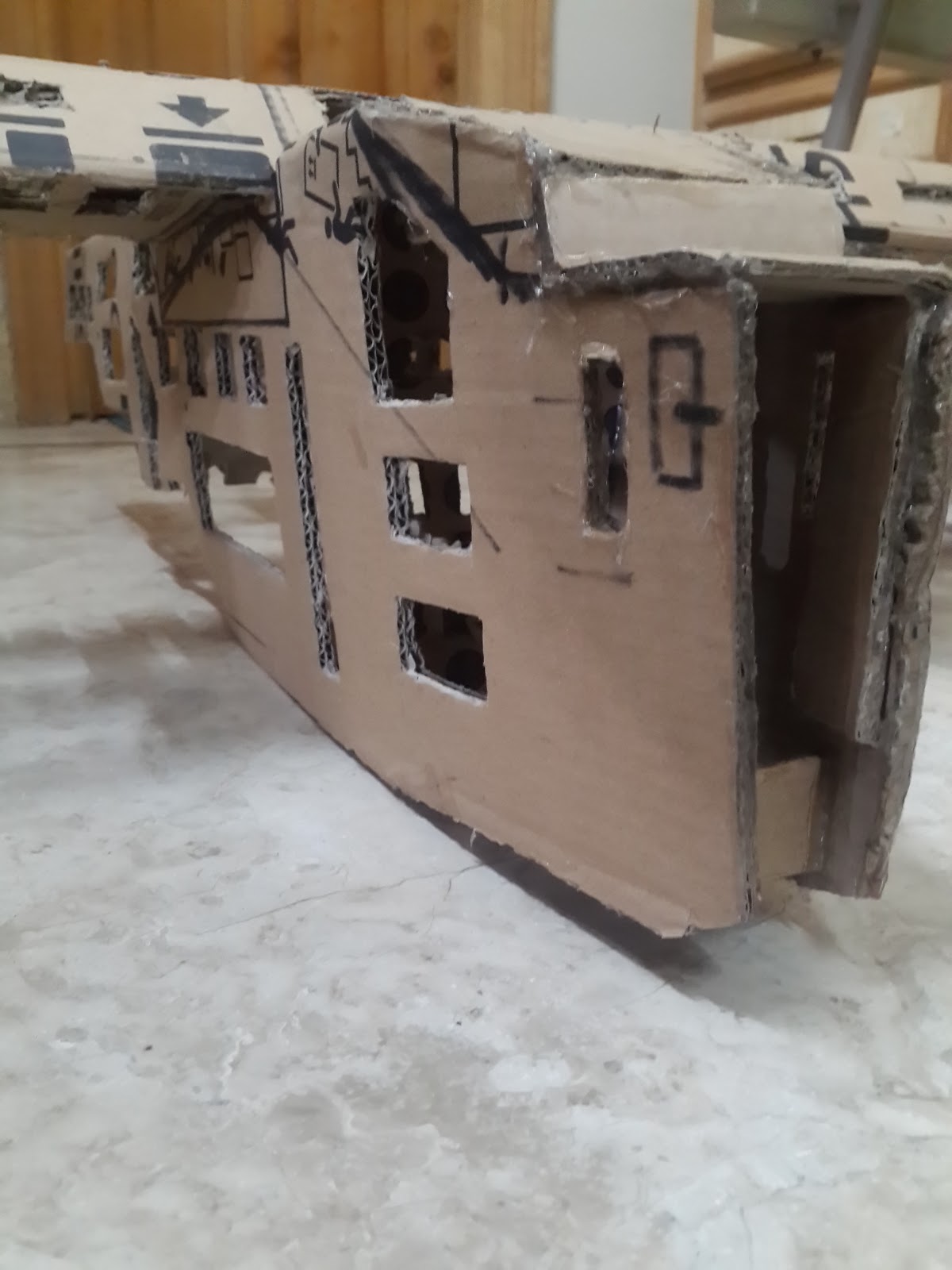
D.I.Y. RC Plane/ Home-made Rc plane from Card Board and Hot Glue (fuselage) 01
There were no servo motors and only two small motors with propellers. Yaw was achieved by changing the throttle on both sides and it was really hard to control.
Then after many years I flew a quad-copter,first, a Nano-quadcopter and then a big one .
Then I thought about making an RC plane and read/watched a-lot of things on-line.but then I couldn't find the foam sheets which are normally used to do this.So now, I'm trying to make it with a card board.
Obviously, it's weight can be and it is, a-lot more as compared to the "usual" foam sheets but I still carried on with it thinking, it will definitely teach me some things about making Rc planes and the future ones might even takeoff more than once :)
However, I have a strong "will" to make it fly (multiple times )no-matter how much "thrust" it requires.
I just want to see this "thing" fly.


TO BE CONTINUED . . . . .
ESP8266 Node MCU (12E) Internet/WiFi Controlled robot/rover using Lm298 H-bridge Motor driver TEST-01
 //****************************************************
 //   Android/fruitPhone Controlled WiFi Car
 //****************************************************


 // ESP 8266 NodeMcu V1.0 PWM Servo/ LM298 H-bridge Control Via WiFi UDP


 //*************************************************
 //*************************************************

 // TEST SKETCH

 // USING LM298's ONLY ONE CHANNEL

 //*************************************************
 //*************************************************


 //****************************************************


 // Using Free Android or iOS App   "RoboRemo"


 //****************************************************


 //***************************************************************


 // PLEASE VISIT


 //****************************************************************


 //       My Blog :  https://amkDiyProjects.BlogSpot.com


 //  My youtube Channel:  https://youtube.com/CrazyGuyOfficial


 //****************************************************************


 //************************************************************


 //  Libraries Required for this to work

 //************************************************************


 #include <ESP8266WiFi.h>
 #include <WiFiUdp.h>
 #include <Servo.h>


 //************************************************************

 // Settings for the WIFI:

 //************************************************************


 const char* ssid = "myWifi";      // Set WiFi Name of WiFi Router/AP/HotSpot AND Esp8266 will connect TO it
 const char* password = "12345678";   // Set PassWord For WiFi


 unsigned int localPort = 9876;     // Set port number


 //************************************************************

 // Settings for Servo using Servo library

 //************************************************************


 const int chCount = 3;
 Servo servoCh[chCount];

 int chPin[] = {5, 4, 14};


 int chVal[] = {1600, 1600, 1600}; // default value in microSeconds for PWM signals (middle)

 int usMin = 700;         // min pulse micro seconds

 int usMax = 2600;         // max pulse micro seconds


 //***************************************************************
 // LM298 H-bridge Motor Driver Pins and Settings for one channel
 //***************************************************************


 int enA = 12 ;         // Pwm signal Pin used to control Motor Speed (Lm298)
 int IN1 = 13 ;         // IN1 IN2 pins on lm298 to control Motor's direction of rotation
 int IN2 = 15 ;
 int mid = 1024 ;         // Default PWM value for enA pin


 //***************************************************************


 char cmd[40];


 // Make a character array/C string to store the Contents Read from the received UDP Packet


 // Cmd is the name of the UDP packet Buffer in which the command which is received is stored


 unsigned long lastCmdTime = 60000;


 unsigned long aliveSentTime = 0;


 //***************************************************************


 WiFiUDP port;


 //************************************************************

 //   SETUP BEGINS

 //************************************************************


 void setup() {

  pinMode(enA, OUTPUT);

  pinMode(IN1, OUTPUT);

  pinMode(IN2, OUTPUT);


  digitalWrite(enA, LOW);
  digitalWrite(IN1, LOW);
  digitalWrite (IN2, LOW);


  delay(500);

  Serial.begin(115200);

  Serial.println("Connecting to ");

  Serial.println(ssid);


  WiFi.mode(WIFI_STA);         //Set Esp8266 in Station mode
  //it can work without this line but necessary for preventing Ap mode (happened in my case )


  WiFi.begin(ssid, password);     // Connect to WiFi network


  while (WiFi.status() != WL_CONNECTED) {

   delay(500);

   Serial.println("trying to connect");

   delay(500);


  }


  Serial.println("");


  Serial.println("WiFi connected");

  port.begin(localPort);


  Serial.print("Use this Ip and Port in RoboRemoApp to connect: ");     //Print the IP address and port number

  Serial.print(WiFi.localIP());

  Serial.print(":");

  Serial.print(localPort);


 }

 //*************************************************
 // SETUP END
 //*************************************************


 //************************************************************

 //   LOOP BEGINS

 //************************************************************


 void loop() {


 //*************************************************


  if (millis() - lastCmdTime > 500) {


 //*************************************************


   analogWrite(enA, 0);  // Write 0 or turn off the pwm signal to the lm298's enA pin so motor stops
   digitalWrite(IN1, LOW);
   digitalWrite(IN2, LOW);


 //*************************************************


   for (int i = 0; i <= 2; ) {


    servoCh[i].detach(); // Turns OFF all the Pins declared in servo library settings above


    i++;
   }

  }


 //*************************************************


  int packetSize = port.parsePacket();  // Declaring an int for getting Packet Size


  if (packetSize > 0) {


   port.read(cmd, 40);


   //Serial.print("CMD");
   //Serial.println(cmd);   // Print the recieved cmd


 //*************************************************

   if (cmd[0] == 'f' && cmd[1] == 'b') {  // if the recieved command string contains the channel id "fb" (forward/backwards)


    exeFB();               // execute the function "FB" so all the pins required to control lm298 can operate
   }


   if (cmd[0] == 'c' && cmd[1] == 'h') {  // if the recieved command string contains the channel id "ch"


    exeServo();   // execute the servo function
             //so Pwm signals according to the channel number can be sent to servos
             // via the GPIO pins declared above in the servo library settings
   }


 //*************************************************


   if (millis() - aliveSentTime > 1000) {


    // an "alive" signal is sent periodically to the phone to know the connection state
    // in the RoboRemo app from "edit UI" option add an "led" or a "text log box" set the ID
    // to "alive" or can be changed but for the text box if left empty the received text will be shown


    exeReply();                    // Execute exeReply function At the end of the loop

   }


  }


 }

 //*************************************************
 // LOOP ENDS
 //*************************************************


 //************************************************************************************

 // FUNCTIONS

 //************************************************************************************

 void exeFB() {

  lastCmdTime = millis();


  int fb = cmd[2] - '0' ;
  int fbVl = 0;


  int i = 4;
  while ( isdigit( cmd[i] ) ) {    // if the 4th character in the Array is a Number
   //get the number and Calculate all the digits in to a single 4 digit number
   fbVl = (fbVl * 10) + (cmd[i] - '0');


   i++;
  }


  if (fb == 3 && cmd[3] == ' ' && fbVl > mid) { // forward motor direction


   digitalWrite(IN1, HIGH);         // set LM298 channel one motor direction
   digitalWrite(IN2, LOW);


   int FWD = map(fbVl, 1025, 2048, 0, 1024); // map the channel value number to a number between 0-1024
                        // for writing Pwm to pin enA


   Serial.print("FWD :");

   Serial.println(FWD);


   analogWrite(enA, FWD);         // write pwm

  }


  if (fb == 3 && cmd[3] == ' ' && fbVl < mid) {    // backwards motor direction

   digitalWrite(IN1, LOW);              // set pins for reverse direction
   digitalWrite(IN2, HIGH);


   int BKW = map(fbVl, 1024, 0, 0, 1024);       //map value

   Serial.print("BKW :");
   Serial.println(BKW);


   analogWrite(enA, BKW);              //write PWM

  }


  Serial.print ("fb Number : ");
  Serial.println (fb);


  Serial.print ("fbVl : ");
  Serial.println (fbVl);


 }


 //******************************************************************************************


 void exeServo() {     // exeCmd function when called from the loop Reads the channel number and value and sends PWM signals

  lastCmdTime = millis();


  int ch = cmd[2] - '0' ; // Channel Number
  int chVl = 0;      // Channel Value temporarily store it in this and then move to Array chVal[] which is already
              // declared at the top


  int i = 4;
  while ( isdigit( cmd[i] ) ) {    // if the 4th character in the Array is a Number
   //get the number and Calculate all the digits in to a single 4 digit number
   chVl = (chVl * 10) + (cmd[i] - '0');

   chVal[ch] = chVl;
   i++;
  }


  if (ch >= 0 && ch <= 2 && cmd[3] == ' ') { //if channel value is between 0 and 9 send PWM Signals using Channel Value


   if (!servoCh[ch].attached()) {

    servoCh[ch].attach(chPin[ch], usMin, usMax);

   }


   servoCh[ch].writeMicroseconds(chVal[ch]);
  }


  Serial.print ("channel Number : ");
  Serial.println (ch);


  Serial.print ("chVl : ");
  Serial.println (chVl);


 }


 //*********************************************************************************************
 void exeReply() {


  port.beginPacket(port.remoteIP(), localPort);  // Send "Alive 1" back to the App to light up the "led" in the App GUI
  // Alive is the "id" for "LED" and "1" is the On command /n" will be ignored
  port.write("alive 1\n");

  port.endPacket();

  aliveSentTime = millis();

  Serial.println("alive sent");

 }
D.I.Y. Make RCA/AV Cable for Raspberry pi (using earphones/headphones audio lead)
Make RCA cable for Raspberry pi
I used an old cell phone's hands-free earphones kit and a female RCA connectors cable to make an AV (audio/video) Cable for the Raspberry Pi.
First, I tried to use a "ready-made" AV cable that I had for a long time and it came with another cell phone (Nokia N95 8GB music edition) but it didn't work at first because the Raspberry pi and that cellphone have different pin-out in the Audio Jack.
So, when I plugged it in the Raspberry Pi 3 and in the TV ,I just got weird noises and no Video . After thinking about it for sometime,I tested it with a multimeter by putting it in the "continuity mode" and in that mode if you touch both of the leads of the multimeter together it shows the number "0" and if there is no connection between the two leads it shows the alphabet "l" which means out-of-limit or range. It actually measures the resistance between it's two leads.So, if there is no connection between the two points i.e. the audio jack's metal pin and the corresponding wires the resistance will be infinite or too high for the meter to measure.
So, if you connect one lead of the multimeter (black or red doesn't matter in this case) to one of the four metal contacts of the Audio lead and the other lead of the multimeter to the RCA connector's outer metal part (Ground) or the center part (which is for the Signal) you can see which part of the Audio lead is connected to which part of the RCA connector.
In my case what was happening was that the Raspberry Pi's Video signal was going to the Ground of the Rca Cable and because ground is common for all the signals (Audio Left,Audio Right ,Video) all the three RCA connectors (red,white,yellow) had Video signal in their outer metal part of the connector and the "Actual Ground" was only on the Signal part in the center of the Yellow connector because of the different pin-out.
However, I made it to work also, just to test the Video output of the Raspberry pi by using a single Male RCA connector with it's wire stripped and by wrapping it on both the outer part of the yellow connector (of that cell phones AV cable) to get the Video Signal and the center part to get the Ground and then it worked but it was too messy.
So,then i felt the need to make a proper AV cable for the pi because I also fixed a cheap LCD display and that display was part of a car's Headrest and meant to be used with the DVD player it came along with(the chinese car DVD player with built-in lcd came with two head rests with LCDs in them ) and it has two analog video inputs so it can work with the Rpi too.
How i made the AV cable can be seen in the picture below.
 |
| Raspberry Pi Audio Jack/RCA Connections Pin-out |
 |
| Cell phone hands-free earphones with button and a Mic and four connector lead |
 |
| Cellphone Earphones with Button and Mic for Calls |
 |
| Female RCA connectors Cable |
 |
| Female RCA Connectors Separated from the "other" lead |
 |
| Separate all the wires and test with a multimeter (on continuity mode) because sometimes the wires are insulated and they have to be "burned" to remove the insulation |
 |
| Test all the wires before proceeding any further just to be sure because it will become difficult to troubleshoot later if there is any problem with the connections |
 |
| Join the related wires together |
 |
| Solder them together and Test them Again |
 |
| Tape the wires separately and then together to make it all neat |
Then I used Male-to-Male RCA cable to connect this to the TV.
You can also use Male to Male RCA cable then cut it,strip it and join with the audio lead the same way and then it will directly connect to the TV giving the same results .
I did it this way because I also had the useless female connectors .
 |
| Car Head-rest Rear LCD for DVD player Front View |
 |
| Back Cover Removed View of LCD and it's control board |
 |
| Main IC on the control board of LCD |
 |
| Back View of LCD control Board and Connectors |
Control motors,Leds,Relays or Motor Driver like lm298 using ESP8266 NodeMcu WiFi UDP with RoboRemo App
//**************************************************** // Android/fruitPhone Controlled WiFi Car //**************************************************** // ESP 8266 NodeMcu V1.0 PWM Servo Control Via WiFi UDP // Using Free Android or iOS App "RoboRemo" //****************************************************// for Controlling LM298 module with 3 pins (one channel) //I have uploaded another sketch after this one see this link with LM298 pins included//****************************************************//*************************************************************** // PLEASE VISIT //**************************************************************** // My Blog : https://amkDiyProjects.BlogSpot.com // My youtube Channel: https://youtube.com/CrazyGuyOfficial //**************************************************************** //************************************************************ // Libraries Required for this to work //************************************************************ #include <ESP8266WiFi.h> #include <WiFiUdp.h> #include <Servo.h> //************************************************************ //************************************************************ // Settings for the WIFI: //************************************************************ const char* ssid = "mywifi"; // Set WiFi Name of WiFi Router/AP/HotSpot AND Esp8266 will connect TO it const char* password = "12345678"; // Set PassWord For WiFi unsigned int localPort = 9876; // Set port number // if it's not working first ensure the following things // to use it in Local network i.e. in the same wifi "client Isolation" should be turned off in the Wifi Router's settings // otherwise even if both the phone and the esp8266 are connected to the wifi they will not be able to "talk to each-other" // to use it from the Internet the port should be forwarded in the WiFi router's settings //************************************************************ // Settings for Servo using Servo library //************************************************************ const int chCount = 4; // 4 channels,total number of channels is 4 and 4 GPIOs will be used Servo servoCh[chCount]; int chPin[] = {5, 4, 14, 12}; // ESP8266 12E NODE MCU DevKit V1.0 pins: GPIO 5, 4, 14, 12 // on my NODE MCU board they are marked D1 D2 D5 D6 respectively // IN THE App first channel "ID" is Ch 0 = 5 ch 1 = 4 ch 2 = 14 ch 3 = 12 int chVal[] = {1600, 1600, 1600, 1600}; // default value in micro-seconds for PWM signals (middle) int usMin = 700; // min pulse micro seconds int usMax = 2600; // max pulse micro seconds //************************************************************ char cmd[40]; // Make a character array/C string to store the Contents Read from the received UDP Packet // Cmd is the name of the UDP packet Buffer in which the command which is received is stored unsigned long lastCmdTime = 60000; unsigned long aliveSentTime = 0; //************************************************************ WiFiUDP port; //************************************************************ // SETUP BEGINS //************************************************************ void setup() { delay(1000); Serial.begin(115200); Serial.println("Connecting to "); Serial.println(ssid); WiFi.mode(WIFI_STA); //Set Esp8266 in Station mode //it can work without this line but necessary for preventing Ap mode (happened in my case ) WiFi.begin(ssid, password); // Connect to WiFi network while (WiFi.status() != WL_CONNECTED) { delay(500); Serial.println("trying to connect"); delay(500); // IF UNABLE TO CONNECT OR IF IT'S TAKING TOO LONG //first CHECK the SSID,PASSWORD in the SKETCH it should be your WIFI name/ssid and PASSWORD //second every-time after uploading a sketch reset esp8266 once or disconnect from power and connect again //and in the second case to view the serial data again //select the device port in Arduino IDE again and turn off/on Serial monitor } Serial.println(""); Serial.println("WiFi connected"); port.begin(localPort); Serial.print("Use this Ip and Port in RoboRemoApp to connect: "); //Print the IP address and port number Serial.print(WiFi.localIP()); Serial.print(":"); Serial.print(localPort); } void loop() { if (millis() - lastCmdTime > 500) { // All PWM values will Return to Default Values 500 milli seconds after the time of Last Received Command // So all PWM signals will return to default values if there is No New Command for (int i = 1; i <= 3; ) { // set i to 0,1,2 or 3 (if connected to servo and want it to stay at the last commanded position) // and rest of the pins PWM signals will return to default values if there is No New Command // Comment out these two lines if you just want to turn the Pwm signals off immediately // and Uncomment if you also want the servo to return to mid but then servo.detach below should be commented // because servo.detach turns the pins off immediately and does'nt give the servo enough time to return to mid // servoCh[i].attach(chPin[i]); // servoCh[i].writeMicroseconds(1600 ); servoCh[i].detach(); // Turns OFF the Pins // comment it out if want the servo to Return to it's mid Position Quickly // because this loop runs over and over again quickly and the servos need some time to //physically move and PWM should be ON during that period // because this line turns off the pin before moving to i++ and changing the pin number i++; } } int packetSize = port.parsePacket(); // Declaring an int for getting Packet Size if (packetSize > 0) { // if Packet Size is more than zero or if there is some command received then port.read(cmd, 40); // Read the Received UDP Packet //and Put the Contents,the channel number and value in the Cmd (array/C string) // Serial.println(cmd); // Print the recieved cmd if (cmd[0] == 'c' && cmd[1] == 'h') { // if the command starts with the caracter c and the second character is h exeCmd(); // Execute the execmd function which is at the end of the loop } if (millis() - aliveSentTime > 1000) { // an "alive" signal is sent periodically to the phone to know the connection state // in the RoboRemo app from "edit UI" option add an "led" or a "text log box" set the ID // to "alive" or can be changed but for the text box if left empty the received text will be shown exeReply(); // Execute exeReply function At the end of the loop } } } void exeCmd() { // exeCmd function when called from the loop Reads the channel number and value and sends PWM signals lastCmdTime = millis(); int ch = cmd[2] - '0' ; // Channel Number int chVl = 0; // Channel Value temporarily store it in this and then move to Array chVal[] which is already declared at the top int i = 4; while ( isdigit( cmd[i] ) ) { // if the 4th character in the Array is a Number //get the number and Calculate all the digits in to a single 4 digit number chVl = (chVl * 10) + (cmd[i] - '0'); chVal[ch] = chVl; i++; } if (ch >= 0 && ch <= 9 && cmd[3] == ' ') { //if channel value is between 0 and 9 send PWM Signals using Channel Value if (!servoCh[ch].attached()) { servoCh[ch].attach(chPin[ch], usMin, usMax); } servoCh[ch].writeMicroseconds(chVal[ch]); } Serial.print ("channel Number : "); Serial.println (ch); Serial.print ("channel Value : "); Serial.println (chVal[ch]); } void exeReply() { port.beginPacket(port.remoteIP(),localPort); // Send "Alive 1" back to the App to light up the "led" in the App GUI // Alive is the "id" for "LED" and "1" is the On command /n" will be ignored port.write("alive 1\n"); port.endPacket(); aliveSentTime = millis(); Serial.print("alive sent"); }
Subscribe to:
Posts (Atom)